View Welding Rectifier Circuit Diagram Pics. I know simple dc tig welder is much. We have studied the operation and i/v characteristics of a pn junction diode in the previous experiment.
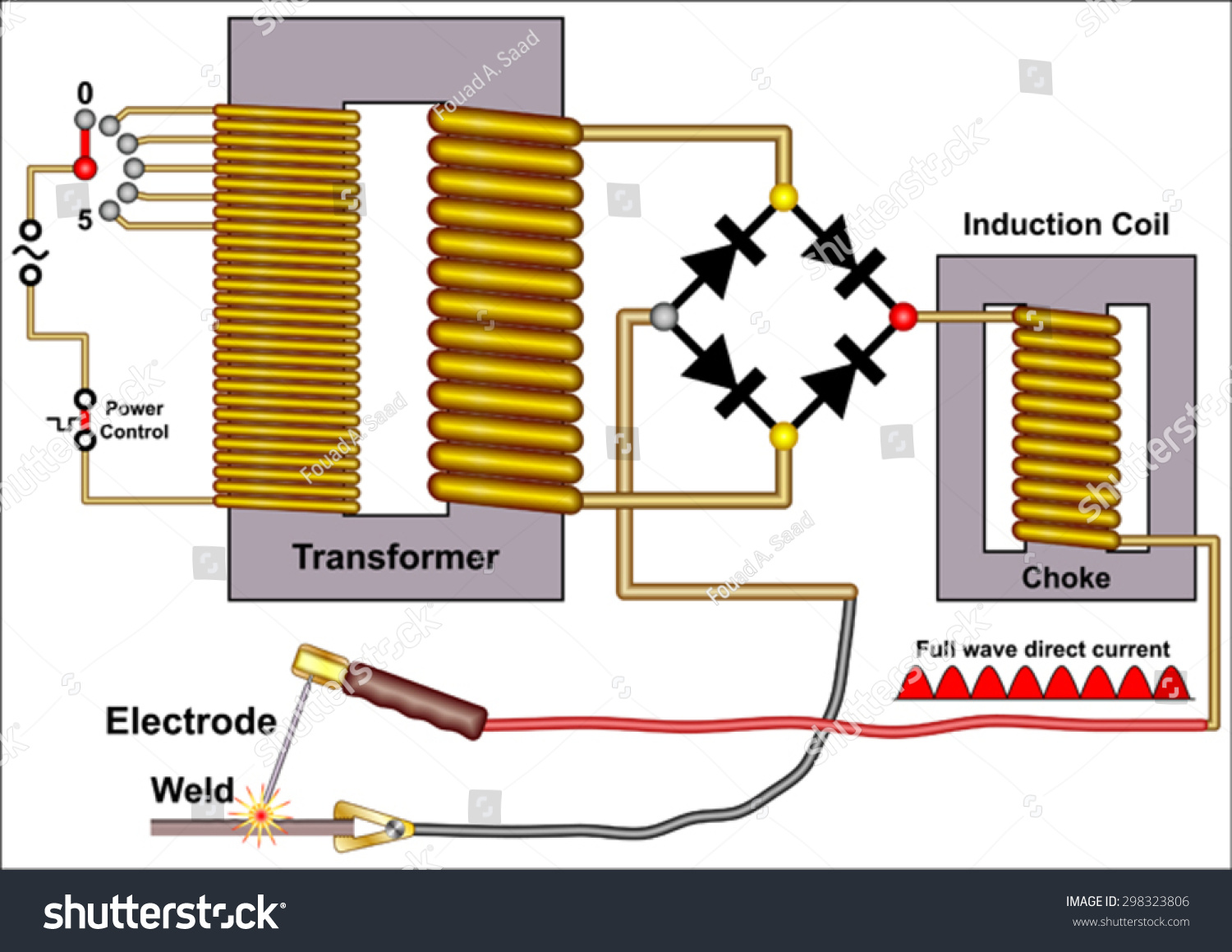
Arc Welding Machine Stock Vector 298323806 - Shutterstock from image.shutterstock.com Most of the industrial power supplies such as dc motor drives, welding units, etc the circuit diagram of three phase full wave rectifier using20l6p45 is very simple and useful for all. A rectifier is an electrical device that converts alternating current, which periodically reverses direction, to direct current (dc), which flows in only. When capacitor filter is added as below, 1.
In electronics, rectifier circuit is the most used circuit because almost every electronic appliance concisely, a rectifier take a current which has both negative and positive components and rectifies it such from the circuit diagram it is apparent that the diodes are connected in a particular fashion.
Most of the industrial power supplies such as dc motor drives, welding units, etc the circuit diagram of three phase full wave rectifier using20l6p45 is very simple and useful for all. See more ideas about electronic schematics, circuit diagram, electronics. A rectifier circuit is a circuit that converts an alternating supply current into a direct output current, a process called rectification. Generally, all these blocks combination is called a regulated dc power supply that powers various electronic appliances.

0 Response to "Welding Rectifier Circuit Diagram"
Post a Comment